Fundamentals
What is the difference between calibration, verification, and adjustment?
Calibration is the full documented comparison against a traceable reference — it produces a certificate with uncertainty statements.
Verification is a simpler pass/fail check confirming the tool is within specification — it does not fully characterize performance.
Adjustment (recalibration) is the act of physically modifying the tool to bring it back within tolerance. ISO 6789 mandates calibration, not merely verification. A tool that passes verification without calibration documentation is not ISO 6789-compliant.
ISO 6789-2:2017
What is torque calibration?
Torque calibration is the process of comparing the output of a torque tool or torque measuring instrument against a known traceable reference standard under controlled conditions. It documents the relationship — including deviation and error — between the measured value and the true value. The result is a calibration certificate that quantifies how accurately the tool performs.
Reference: ISO 6789-2:2017 §3 — Definitions
Why is torque calibration important?
Improperly torqued fasteners are a leading cause of joint failure, product recalls, and liability across automotive, aerospace, medical device, and industrial sectors. Calibration ensures that when a technician sets 100 N·m, the actual applied torque is within an accepted tolerance. It protects product and joint integrity, worker and end-user safety, compliance with audits (ISO 9001, IATF 16949, AS9100), and legal defensibility in case of field failure.
What is metrological traceability?
Traceability means the calibration result can be related to a national or international measurement reference through a documented, unbroken chain of comparisons — each with stated measurement uncertainty. Your torque wrench was calibrated by a transducer calibrated by a higher-level standard, ultimately traceable to a National Metrology Institute (NML in Taiwan, PTB in Germany, NIST in USA). Without this chain, the calibration has no internationally recognized validity.
ISO/IEC 17025:2017
What types of torque tools require calibration?
All torque-applying or torque-indicating tools used in quality-critical applications require periodic calibration: click-type torque wrenches, dial/beam/indicating wrenches, electronic/digital torque wrenches, torque screwdrivers, preset wrenches, torque multipliers (with calibrated input/output ratio), pneumatic/pulse tools (calibrated via external transducer), and torque transducers and analyzers used as measuring instruments.
ISO 6789 Standard
What accuracy tolerances does ISO 6789 specify?
Type I (indicating) tools: ±4% of the reading at each calibration point throughout the working range.
Type II (setting) tools: ±4% of the set torque value. These tolerances apply to the
mean of 5 consecutive measurements at each loading point. Individual readings may vary, but the mean must fall within ±4%.
ISO 6789-2:2017
At what torque values must calibration be performed?
ISO 6789-2 requires at least 3 loading points: 20%, 60%, and 100% of maximum torque capacity (or the operating set point). Each point requires 5 preloading cycles followed by 5 measurement readings. The arithmetic mean of the 5 readings is compared to the reference value.
ISO 6789-2:2017
What must appear on an ISO 6789-compliant calibration certificate?
A compliant certificate must include: unique certificate number and issue date; tool identification (make, model, serial number, range, resolution); reference to ISO 6789-2:2017; calibration results at each loading point (mean, deviation from nominal, expanded uncertainty); measurement uncertainty statement with coverage factor
k; environmental conditions (temperature, humidity); reference standards used with traceability chain; lab accreditation body and number; and statement of conformity with decision rule applied.
ISO 6789-2:2017
What is ISO 6789 and what does it cover?
ISO 6789 is the international standard for manually operated torque tools, structured in two parts:
ISO 6789-1:2017 — design and quality conformance testing (type testing for manufacturers);
ISO 6789-2:2017 — requirements for calibration and determination of measurement uncertainty. Part 2 is the operationally critical document for distributors, end-users, and calibration laboratories. The 2017 edition introduced formal uncertainty requirements absent in the 2003 version.
ISO 6789-1:2017 / ISO 6789-2:2017
What are the main changes in ISO 6789:2017 vs the 2003 version?
Key changes: formal
measurement uncertainty requirements introduced (2003 had none); standard split into two parts; expanded classification of tool types with clearer sub-classes; stricter calibration documentation and interval requirements; closer alignment with ISO/IEC 17025. Any certificate without an uncertainty statement was likely performed to the obsolete 2003 edition and is non-compliant for current quality audits.
ISO 6789-2:2017 Foreword
How does ISO 6789 classify torque tool types?
Type I — Indicating tools (measure and display torque): Class A — direct reading (dial, beam); Class B — peak memory / electronic display.
Type II — Setting tools (signal when preset torque is reached): Class A — audible signal (click); Class B — slip/breaking; Class C — torsion bar deflection; Class D — electronic signal; Class E — dial preset.
ISO 6789-1:2017 §4
What calibration interval does ISO 6789 require?
ISO 6789-2 does not specify a fixed mandatory interval, but requires recalibration after first use/commissioning, any repair/damage/suspected overload, or after a defined time interval or number of operations. Industry practice is typically
12 months for moderate use. High-intensity users (automotive assembly, 5,000+ cycles/year) often recalibrate every 6 months or after a defined operation count.
ISO 6789-2:2017 §4
ISO/IEC 17025 Lab Accreditation
What is ISO/IEC 17025 and how does it differ from ISO 9001?
ISO/IEC 17025 is the international standard for the
competence of testing and calibration laboratories. While ISO 9001 governs quality management systems across any organization, ISO/IEC 17025 specifically assesses technical competence — whether a lab can produce valid, traceable measurement results. A lab can be ISO 9001-certified but lack the technical capability to calibrate torque tools accurately. IATF 16949 and AS9100 auditors specifically require ISO/IEC 17025-accredited calibration for measuring equipment.
ISO/IEC 17025:2017 §1
What are the key requirements of ISO/IEC 17025 for a torque calibration lab?
The standard imposes requirements in five domains:
Organization (impartiality, confidentiality);
Resources (personnel competency, equipment calibration, environmental conditions, traceability);
Process (method selection, sampling, handling, uncertainty estimation, data integrity);
Management system (document control, corrective action, internal audit); and
Reporting (calibration certificate content and conformity statements). A lab passing all five demonstrates both technical competence and system integrity.
ISO/IEC 17025:2017 §4–8
What is a Calibration and Measurement Capability (CMC) statement?
CMC (also called best measurement capability) is the smallest uncertainty a calibration lab can achieve under optimal conditions, formally stated in its published Scope of Accreditation. For torque calibration, a lab's CMC might be stated as e.g. 0.3% of reading (k=2) across a defined range. Customers and auditors should verify that the lab's CMC is at least 4× smaller than the tool's tolerance (the 4:1 TUR rule). A lab without a published CMC for torque is not accredited for that measurement type.
What is a Scope of Accreditation and how should audit reviewers interpret it?
The Scope of Accreditation is a formal document issued by the accreditation body listing exactly which measurement types, ranges, and uncertainties the lab is accredited to perform. Reviewers must verify three things: (1) measurement type — torque must be explicitly listed, not just force or general mechanical; (2) measurement range — must cover the tools being calibrated; (3) CMC — uncertainty must be consistent with the 4:1 TUR requirement. Calibration performed outside the stated scope is not covered by the accreditation, even if performed by the same lab.
What is proficiency testing and why is it required under ISO/IEC 17025?
Proficiency testing (PT) is an external verification where a lab measures a reference artifact alongside other labs, and its results are compared to a reference value and to peer results. ISO/IEC 17025:2017 §7.7 requires labs to participate in PT programs to demonstrate ongoing measurement validity. For torque, this typically involves circulating a reference torque transducer among participating labs. Auditors should ask: "What PT programs does your lab participate in, and what were the most recent results?"
What are the main accreditation bodies for calibration labs globally and in Taiwan?
Key national accreditation bodies include:
- CNLA / TAF — Taiwan Accreditation Foundation (台灣認證基金會)
- UKAS — United Kingdom Accreditation Service
- DAkkS — Deutsche Akkreditierungsstelle (Germany)
- A2LA — American Association for Laboratory Accreditation (USA)
- JCSS / IAJapan — Japan Calibration Service System
- ILAC MRA — Mutual Recognition Arrangement linking all above bodies
A certificate from any ILAC MRA signatory is internationally recognized. Always verify the lab's accreditation number on the accreditation body's public database.
What is the difference between an accredited calibration and a traceable calibration?
Traceable calibration means the measurement chain can be linked to a national standard — a necessary but not sufficient condition. Accredited calibration means the calibration was performed by a lab independently assessed as technically competent per ISO/IEC 17025 — it implies traceability plus verified competency, methods, uncertainty estimation, and quality system. IATF 16949 §7.1.5.2 explicitly requires calibration to a national/international standard with stated measurement uncertainty — in practice this means accredited calibration.
DIN & JIS Equivalents
What are the DIN standards equivalent to ISO 6789 for torque tools?
The principal German DIN standards in this domain are:
- DIN ISO 6789-1 — German adoption of ISO 6789-1 (identical content)
- DIN ISO 6789-2 — German adoption of ISO 6789-2 (identical content)
- DIN EN ISO 6789 — EN-level harmonized adoption (used in European CE context)
- A legacy German engineering association guideline covering torque wrench calibration procedures, pre-ISO 6789:2017, still referenced in some German automotive supplier contexts
For CE-marked products and IATF 16949 contexts in Europe, DIN EN ISO 6789 is the operative reference.
DIN ISO 6789-1:2017 / DIN ISO 6789-2:2017
What are the JIS standards equivalent to ISO 6789 for torque tools?
Japan Industrial Standards covering torque tools include:
- JIS B 4652:2008 — Hand torque tools: requirements and test methods, covering both torque wrenches and torque screwdrivers
- Torque meters (transducers and analyzers) are covered under a separate JIS standard
JIS B 4652:2008 is the current calibration reference for hand torque tools in Japanese industrial practice - it superseded the earlier JIS B 4650:2002 (torque wrenches only), which was withdrawn in 2008. Its accuracy tolerance is ±4% of set/indicated value — consistent with ISO 6789.
JIS B 4652:2008
How do DIN/JIS accuracy tolerances compare to ISO 6789?
All three systems converge on the same core tolerance:
±4% of the set or indicated value. Differences lie in procedural details:
- ISO 6789-2:2017: 5 preload cycles + 5 measurement readings; formal uncertainty statement mandatory
- JIS B 4652:2008: 5 preload cycles + 5 readings; uncertainty statement not explicitly required at the same depth
- Legacy German guidelines (pre-ISO 6789:2017): 3–5 readings; no formal uncertainty requirement
An ISO 6789-2:2017 certificate satisfies DIN EN ISO 6789 and generally satisfies JIS B 4652:2008 where core tolerance compliance is the criterion.
Can a tool calibrated to JIS B 4652:2008 be accepted in an ISO-audited environment?
It depends on the audit scheme. If the quality system requires calibration traceable to national or international standards with stated measurement uncertainty, a JIS B 4652:2008 certificate from a JCSS-accredited lab (ILAC MRA signatory) is generally acceptable. However: if the certificate lacks a measurement uncertainty statement, auditors operating strictly to ISO/IEC 17025 requirements may raise a finding. Best practice: specify in supplier qualification documents that any calibration certificate must include an expanded uncertainty statement with coverage factor k, regardless of which national standard is referenced.
What is the legacy German torque calibration guideline referenced before ISO 6789:2017, and when is it still relevant?
This is a German engineering association guideline covering torque wrench calibration procedures, published prior to the major 2017 revision of ISO 6789. It specifies similar ±4% tolerances but with less rigorous uncertainty requirements. It remains relevant in legacy German supplier qualification packages not yet updated to ISO 6789:2017, some tool manufacturer type-test protocols issued before 2017, and internal in-house calibration procedures at medium-sized German industrial companies that have not yet transitioned. Auditors should flag references to this legacy guideline as potentially outdated if the supplier cannot demonstrate equivalence to ISO 6789-2:2017 uncertainty requirements.
Practical Calibration Procedures
What is the standard procedure for calibrating a click-type torque wrench?
Per ISO 6789-2, the procedure is: (1) Acclimatize tool for ≥1 hour at 18–28°C; (2) Set to the calibration loading point; (3) Perform 5 preloading cycles to seat the mechanism; (4) Apply torque smoothly and record peak value at click event; (5) Repeat for 5 consecutive measurements; (6) Calculate mean, standard deviation, and deviation from set point; (7) Compare mean to ±4% tolerance band; (8) Repeat for all required loading points (20%, 60%, 100% of range).
ISO 6789-2:2017
What is the correct direction of torque application during calibration?
Tools must be calibrated in the direction of intended use. For right-hand thread (clockwise) tools, calibrate clockwise. If a tool is rated for dual-direction use, both CW and CCW directions must be calibrated — do not assume symmetry. Most click-type wrenches behave differently in each direction; the difference can exceed 4%. A certificate covering only one direction does not represent bidirectional performance.
ISO 6789-2:2017
What environmental conditions must be maintained during calibration?
ISO 6789-2 requires: temperature 18–28°C with maximum variation of ±1°C per hour; reference temperature 20°C; humidity documented and reported (typically 45–75% RH); vibration-free surface; no direct airflow across the transducer. The tool must be thermally stable at lab temperature before calibration begins. Temperature affects both the tool mechanism and the transducer output.
ISO 6789-2:2017
How many preloading cycles are required before taking calibration readings?
A minimum of
5 preloading cycles at each calibration loading point before recording readings. Preloading conditions the internal mechanism, eliminates hysteresis from the previous set point, and ensures a repeatable operating state. For new tools or tools repositioned to a new set point, additional preloading is advisable. Skipping preloading is one of the most common calibration errors in non-accredited shops.
ISO 6789-2:2017
Can a torque tool be recalibrated in the field?
In general, no. ISO 6789-compliant calibration requires a controlled laboratory environment, a traceable Class 0.5 reference transducer, documented procedures, and trained personnel. Field verification devices (check testers) can confirm a tool is approximately within specification, but they do not constitute calibration. Any tool failing field verification must be removed from service and sent to an accredited laboratory before returning to production.
ISO 6789-2:2017
Equipment & Traceability
What calibration equipment is required by ISO 6789?
Primary equipment: a reference torque transducer with Accuracy Class 0.5 or better (total error ≤0.5%), measurement range covering all tools to be calibrated, and a valid traceable calibration certificate. Supporting equipment: torque analyzer/display with appropriate resolution; drive socket adapters matching service use; rigid torque reaction arm/fixture; calibrated thermometer and hygrometer.
ISO 6789-2:2017
What is the difference between a Class 0.5 and Class 1 torque transducer?
Transducer classes refer to maximum permissible total error: Class 0.1/0.05 = reference laboratory level;
Class 0.5 = maximum error ≤0.5%, minimum required for ISO 6789-2 calibration reference; Class 1 = maximum error ≤1.0%, suitable for field verification only, not formal calibration. Using a Class 1 transducer for ISO 6789 calibration is a common nonconformance found in quality audits.
ISO 6789-2:2017
What does the torque traceability chain look like?
Level 1: National Metrology Institute (NML Taiwan / PTB Germany / NIST USA) — primary torque standard machine. Level 2: Class 0.1 transfer standard calibrated at NMI. Level 3: Accredited calibration lab — Class 0.5 working transducer calibrated by Level 2. Level 4: Customer's torque tool calibrated by Level 3 lab. Each link introduces uncertainty, documented with expanded uncertainty and coverage factor k.
How does the drive square adapter affect calibration accuracy?
Drive adapters and extension bars introduce friction and geometric uncertainty. ISO 6789-2 requires the drive system used during calibration to be the same type as used in service, or documented corrections must be applied. Common error sources: poor-fitting/worn adapter sockets (1–3% error), extension bars deflecting under load (off-axis bending moment), and damaged drive square faces adding friction.
Measurement Uncertainty
What is measurement uncertainty and why does ISO 6789:2017 require it?
Measurement uncertainty is a quantitative expression of doubt about the accuracy of a measurement result — it defines the range within which the true value is expected to lie at a stated confidence level. ISO 6789-2:2017 requires it because a result without uncertainty is incomplete. Without uncertainty, a calibration certificate cannot support a valid conformity decision under ISO/IEC 17025.
ISO 6789-2:2017
What are the main sources of uncertainty in torque calibration?
Key uncertainty contributions: reference transducer (stated in its certificate — Type B); display resolution (Type B); tool repeatability — standard deviation of 5 consecutive readings (Type A); temperature effects on mechanism and transducer; adapter and fixture losses; operator influence (application speed, loading angle, handle grip point). Combined using RSS method for uncorrelated components to give combined standard uncertainty
uc.
ISO 6789-2:2017 Annex A
What does a coverage factor of k=2 mean on a calibration certificate?
A coverage factor
k=2 means expanded uncertainty
U = 2 ×
uc. At
k=2, approximately
95% confidence — the true value lies within ±U with 95% probability. This is the standard reporting convention. Some certificates use
k=2.576 for 99% confidence. Always check the stated
k — a certificate reporting ±X% without stating
k is incomplete per ISO/IEC 17025.
ISO/IEC 17025:2017 §7.8.4
What is guard banding and when must it be applied?
Guard banding is a decision rule that shrinks the acceptance zone by the calibration uncertainty to ensure that accepted tools genuinely comply. Instead of accepting a tool if its error is within ±4%, with guard banding at k=2 you only accept if the error is within ±(4% − U%). This prevents a tool at exactly the tolerance limit from being incorrectly passed. ISO/IEC 17025:2017 §7.8.6 requires the decision rule to be stated on the certificate.
ISO/IEC 17025:2017; ILAC G8:09/2019
Commercial & Distributor
What is the commercial value of selling calibrated torque tools vs. uncalibrated?
Calibrated tools create: recurring revenue through annual recalibration contracts; deeper relationships by positioning the distributor as a quality partner; access to QA managers and procurement beyond the tool buyer; and compliance-driven demand — customers in automotive, aerospace, and medical sectors cannot legally avoid calibration. A calibration services program creates a defensible recurring revenue stream competitors without calibration capability cannot easily replicate.
What questions should a distributor ask when a customer says calibration is unnecessary?
Surface the real risk: "When was it last calibrated?" — new tools still require initial calibration. "What torque tolerance does your assembly specification require?" "Are you subject to ISO 9001, IATF 16949, AS9100, or medical device audits?" "Has the tool ever been dropped, overloaded, or repaired?" "Do your customers or end-product inspectors require calibration records?" These questions shift the conversation from "cost of calibration" to "cost of an audit finding or field failure."
How should distributors advise customers on calibration intervals?
Recommend a risk-based approach. Key factors: usage frequency (500 vs. 5,000 cycles/year dramatically changes wear rate); application criticality (safety-critical joints require shorter intervals); storage and environmental conditions; and regulatory requirements (IATF 16949 requires documented, risk-justified intervals). A defensible starting policy: 12-month interval, reviewed against out-of-tolerance history. Tools never found OOT after 3 cycles may be extended to 18 months with documented justification.
What documentation package should accompany a torque tool sold to quality-conscious customers?
A complete package includes: ISO 6789-2:2017-compliant calibration certificate from an accredited lab; tool serial number, model, and capacity specifications; manufacturer accuracy specification/product datasheet; lab accreditation number and scope reference; recommended calibration interval; user instruction and maintenance manual; and optionally, calibration return program enrollment — creating ongoing contact and service revenue.
How should a distributor handle a customer's out-of-tolerance calibration result?
The correct response: (1) Confirm the OOT result is genuine — ask for raw calibration data; (2) Determine which production work used the OOT tool and the affected time period; (3) Customer must perform a nonconformance evaluation on affected products/joints; (4) Remove tool from service immediately; (5) After adjustment and recalibration, document the return to service. An OOT finding is a potential product recall or liability event in regulated industries — documentation is mandatory.
ISO 9001:2015 §8.7
Audit & Compliance Reviewers
What calibration records must be available during an IATF 16949 audit?
IATF 16949 §7.1.5.2 requires: a calibration record for each measuring instrument; the calibration certificate with traceability statement, uncertainty, and conformity decision; the calibration interval and basis for that interval; any out-of-tolerance history and associated nonconformance records; and evidence that tools are identified (serial numbers, labels, stickers) and controlled. Auditors commonly request the calibration register — a master list of all tools, calibration due dates, and certificate numbers.
IATF 16949:2016 §7.1.5.2.1
What are the most common calibration-related audit nonconformances?
The most frequently cited findings in IATF 16949 and ISO 9001 calibration audits:
- Calibration certificates lacking measurement uncertainty statements
- Calibration performed by non-accredited labs or without traceability evidence
- Calibration intervals not documented or not risk-justified
- Tools used beyond calibration expiry dates
- OOT findings with no retrospective product impact assessment
- No calibration ID label or sticker on the tool itself
- Drive adapters and extension bars not included in calibration scope
How should a calibration interval be documented and justified?
The interval must be: documented — written in a procedure, calibration plan, or individual tool record; risk-justified — based on documented factors such as usage frequency, application criticality, past OOT history, and manufacturer recommendation; and reviewed periodically — shortened if OOT history increases, potentially extended if consistently in-tolerance. Intervals set as "12 months" with no further justification may be challenged. Auditors expect a documented rationale — even a simple risk matrix meets the requirement.
What constitutes a calibration management system for audit purposes?
A calibration management system (CMS) must demonstrate: an inventory of all measuring equipment requiring calibration; a schedule with due dates; a system to prevent use of out-of-calibration tools (labels, software lockouts, or physical removal); a procedure for handling OOT results; storage of calibration records for a defined retention period; and periodic management review of calibration performance. ERP calibration modules, specialized gage management software, or even a controlled spreadsheet can satisfy this — the key is documented, consistent execution.
What is the difference between a major and minor calibration nonconformance?
In most audit schemes (IATF 16949, AS9100, ISO 9001):
Major: Systemic failure — e.g., no calibration system exists; tools demonstrably used out-of-calibration with no investigation; certificates completely lacking traceability; no record of OOT impact assessment. A major finding typically requires immediate corrective action before certification proceeds.
Minor: Isolated instance — e.g., one tool found with expired calibration sticker but records exist; certificate missing humidity data. Multiple minors on the same topic may be elevated to a major in subsequent audits.
How should an auditor verify that a torque transducer itself is properly calibrated?
Request: the transducer's own calibration certificate; the accreditation number and scope of the lab that calibrated the transducer; confirmation that the transducer's calibration range covers the tools being calibrated; and the transducer's accuracy class (must be Class 0.5 or better per ISO 6789-2). Cross-check the transducer serial number on the certificate against the physical transducer. Verify the certificate was issued within the defined recalibration interval (typically 12 months for working standards).
Customers & End-Users
How do I know if my torque wrench needs calibration?
Key indicators: the last calibration date exceeds 12 months (or the manufacturer's recommended interval); the tool has been dropped, struck, or overloaded; there are signs of physical damage (bent handle, loose mechanism, scratched scale); the tool feels different — unusual resistance, inconsistent click feel, or erratic behavior; or you have moved to a new application with a different torque range. When in doubt, calibrate — the cost of calibration is always lower than the cost of a failed joint or a quality audit finding.
What should I do if I drop a torque wrench?
Remove the tool from service immediately. Dropping a torque wrench — even once from a moderate height — can: misalign the click mechanism spring; permanently deform the beam or torsion element; shift the preset calibration; and introduce internal hairline cracks. The tool must be sent for recalibration before being returned to use. Never assume a tool is still accurate after an impact event without verified calibration. Tag the tool "Out of service — impact event" until a calibration certificate is reissued.
How should I store a torque wrench between uses?
Store at the lowest torque setting on the scale (not at zero — maintaining at minimum scale position is correct per most manufacturers). Store in the supplied case or protective sleeve. Avoid humidity and extreme temperature. Never hang the wrench by its drive square — this stresses the drive mechanism geometry. Never leave a wrench at a high set torque for extended periods — prolonged spring compression causes drift and early fatigue. These practices directly affect how long the tool retains its calibrated accuracy between intervals.
What does it mean when a calibration report says "found out of tolerance"?
"Found out of tolerance" (OOT or FOUT) means the tool's measured error exceeded the ±4% tolerance band when it arrived at the lab — before any adjustment. This means the tool was producing inaccurate torque during the period since its last calibration. You need to: identify which joints or assemblies were torqued with this tool and when; evaluate whether those joints are safety-critical; perform a nonconformance assessment; and document the investigation. Do not simply recalibrate and move on without this investigation.
How do I read a torque wrench calibration certificate?
Focus on these five fields: (1) Tool ID — verify the serial number matches your physical tool. (2) Calibration results table — shows deviation (%) at each loading point; all must be within ±4%. (3) Expanded uncertainty — stated as ±X% at k=2; the smaller this is, the higher-quality the calibration. (4) Statement of conformity — should say "Compliant" or "Meets ISO 6789-2:2017" with the decision rule stated. (5) Accreditation number — verify this on the accreditation body's public website.
What is the difference between a torque wrench and a torque tester?
A torque wrench is a tool-setting device — it applies torque to a fastener. A torque tester (or torque analyzer) is a measuring instrument — it measures the output of a torque wrench without applying torque to a fastener. Torque testers are used for in-house verification of wrench performance between formal calibrations. The torque tester itself must also be calibrated — using an uncalibrated tester to check a wrench creates a circular uncertainty problem.
Engineers & Technicians
What is the K-factor (nut factor) and how does it relate to torque calibration?
The K-factor (also called the nut factor or torque coefficient) relates applied torque to resulting bolt clamp force: T = K × d × F, where T is torque, d is bolt diameter, and F is clamp force. K is influenced by thread friction, under-head friction, surface finish, lubricant, and plating. Even with a perfectly calibrated torque wrench, clamp force variation of ±25–30% is typical due to K-factor scatter. This is why torque calibration ensures consistent torque input but does not guarantee consistent clamp force output — the fundamental argument for direct bolt load measurement tools like the ZIPPTORK BLT.
What is the difference between static and dynamic torque calibration?
Static calibration applies torque slowly and holds — measurement is made under stable load conditions. ISO 6789 specifies static calibration. Dynamic torque occurs during actual fastening — tool output fluctuates due to inertia, pulse events (impact/pulse tools), and rotational speed effects. A torque wrench calibrated statically may perform differently under actual dynamic assembly conditions. For pulse tools and impact wrenches, a dynamic torque transducer (high-frequency data acquisition) is required — ISO 6789 does not cover these; separate methods per ISO 5393 apply.
How do I calculate the torque error contribution from friction in an extension arm?
For a simple extension bar (rigid, coaxial), the torque transmitted equals applied torque minus friction losses at the connection points. The dominant loss is from the drive square interface, estimated empirically at 0.5–2% per connection. For a calculation approach: apply the wrench at a reference point, measure actual output torque with a transducer at the work end, and record the ratio. This correction factor is then applied to subsequent torque specifications when using that extension configuration. Always recalibrate whenever the extension configuration changes.
What is torque measurement repeatability and how is it quantified?
Repeatability is the variation in measured torque values under identical conditions: same operator, same tool setting, same transducer, short time interval. It is quantified as the standard deviation (σ) of n consecutive readings. ISO 6789-2 uses the mean of 5 readings; the standard deviation of those 5 readings contributes to the Type A uncertainty component. A well-maintained click wrench typically shows repeatability of 0.5–1.5%. Poor repeatability (>2%) indicates mechanism wear, contamination, or spring fatigue and warrants inspection before calibration.
How do I set up an in-house torque tool verification station?
Minimum requirements: a Class 0.5 or Class 1 torque transducer (Class 0.5 for formal calibration, Class 1 for verification only) with current traceable calibration certificate; a rigid reaction fixture aligned to the drive axis; a torque analyzer with peak-hold function; a temperature-controlled environment (18–28°C); and a documented verification procedure with acceptance criteria. Define whether the station is for verification (pass/fail check) or formal in-house calibration — the latter requires a documented quality system and uncertainty budget to hold up in audits.
How do I compensate for extension bar effects on torque output?
When using a rigid coaxial extension, output torque at the fastener equals wrench set torque minus friction losses — typically acceptable for most applications. For handle extensions (bars that extend the wrench handle to change mechanical advantage), the relationship changes: actual output torque = set point × (original handle length / new effective handle length). A 200 mm handle extension on a 400 mm wrench changes mechanical advantage by 1.5× — the wrench must be set to 67% of target torque. Always confirm with a transducer measurement.
What is Gauge R&R (GR&R) in the context of torque measurement?
Gauge Repeatability and Reproducibility (GR&R) is a statistical study that quantifies variation contributed by the measurement system versus the true part-to-part variation. In torque measurement: Repeatability — variation from the same operator using the same transducer multiple times. Reproducibility — variation between different operators or transducers. Per AIAG MSA guidelines: a GR&R study result of <10% of tolerance is acceptable; 10–30% may be acceptable depending on criticality; >30% is unacceptable and the measurement system requires improvement. GR&R studies are required for torque measurement systems in IATF 16949 environments.
ZIPPTORK Products (STA & BLT)
How does the ZIPPTORK STA wireless torque sensor fit within the ISO 6789 framework?
The ZIPPTORK STA functions as a Type I Class B indicating torque instrument — it records and wirelessly transmits the peak torque of each fastening cycle. For the STA to serve as a quality record: the STA must be periodically calibrated against a traceable reference transducer; calibration follows ISO 6789-2 Type I methodology; each STA unit carries a unique serial number enabling certificate-level traceability. The STA enables 100% fastening data capture — turning torque calibration from a periodic check into a continuous fastening quality record.
Can the STA verify whether a click-type wrench is within ISO 6789 tolerance?
Yes, with an important qualification. By mounting the STA inline between the wrench drive and a reaction fixture, each click event generates a peak torque reading. If 5 consecutive readings at a given set point all fall within ±4% of nominal, the wrench passes the ISO 6789 verification criterion. However: this constitutes in-process verification, not a formal accredited calibration. It does not replace laboratory calibration for certificate issuance. Position as "continuous tool health monitoring between formal calibrations."
How should distributors position the ZIPPTORK BLT bolt load transducer relative to torque calibration?
The BLT addresses a fundamental limitation of torque-only control: torque ≠ clamp force. Due to friction variability (thread friction, under-head friction), even a perfectly calibrated torque wrench can produce ±25–30% variation in actual bolt clamp force. The BLT measures actual bolt elongation and clamp force directly, independent of friction. Position it as "the next layer above torque calibration" — essential for safety-critical joints where clamp force is the true engineering parameter and the foundation of Bolt Lifecycle Monitoring (BLMS).
What calibration documentation should accompany ZIPPTORK instruments for audit purposes?
Each ZIPPTORK STA or BLT instrument should ship with: (1) a traceable calibration certificate identifying the instrument by serial number; (2) reference to the calibration standard applied (ISO 6789-2 for STA; force/strain measurement standards for BLT); (3) calibration results with uncertainty statements; (4) the accreditation number of the calibrating laboratory; (5) a recommended recalibration interval; and (6) a calibration history log. This documentation package satisfies IATF 16949 §7.1.5.2.1 requirements for monitoring and measurement equipment records.
How does ZIPPTORK's wireless torque data stream support ISO/IEC 17025 quality objectives?
The STA wirelessly transmits timestamped peak torque values for each fastening event, creating a continuous, tamper-evident fastening record. This supports quality system objectives by: providing objective evidence of torque application for every joint (not just sampled); enabling trend analysis to detect tool drift between calibrations; generating audit-ready data archives with operator ID, timestamp, and torque value; and triggering real-time alerts when torque values fall outside specification bands. This positions ZIPPTORK as a measurement system, not merely a tool — elevating the commercial conversation to the quality management level.
ZIPPTORK TTES Wireless Rotary Torque Transducer
What is the ZIPPTORK TTES and what makes it a rotary torque transducer?
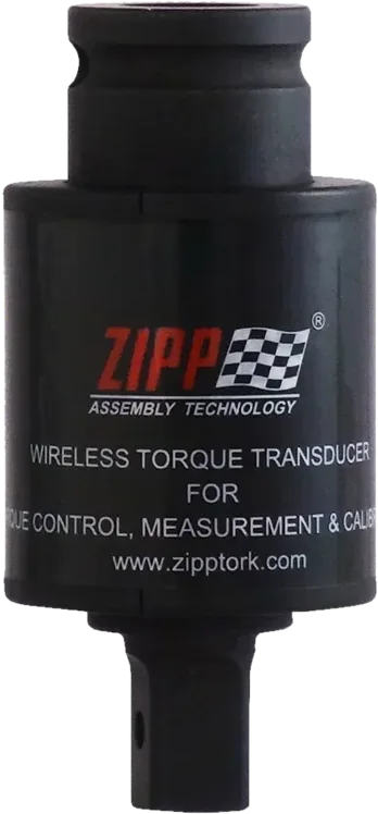
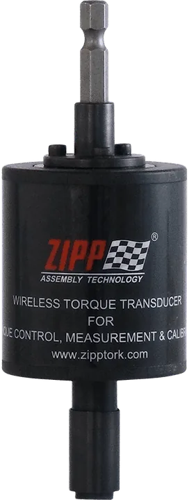
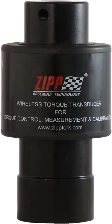
The ZIPPTORK TTES is a wireless rotary torque transducer — meaning the sensing element physically rotates together with the tool or drive shaft during measurement. Unlike a static (reaction) transducer that is fixed to a bench, the TTES is mounted inline between the drive tool and the fastener, spinning continuously as torque is applied. It wirelessly transmits either peak torque (the maximum value reached during a tightening event) or real-time continuous torque readings to a receiver or connected PC. The TTES covers torque measurement only — it does not capture angle of rotation. Available in both Bluetooth and 2.4 GHz wireless variants across a full range of torque capacities.
What torque range and model variants does the TTES series cover?
The TTES series covers a torque range of 0.5 N·m to 3,000 N·m across multiple models. Each model is sized for a specific torque band — enabling accurate measurement across low-torque precision applications (electronics, medical devices, small fasteners) and high-torque heavy industrial applications (structural fastening, automotive assembly, industrial machinery). Two wireless technology variants are available per torque range: Bluetooth — shorter range, suited for bench-level calibration and close-proximity process monitoring; 2.4 GHz — extended range, suited for production floor environments with multiple simultaneous tools or longer distances between transducer and receiver.
What are the accuracy specifications of the TTES and how do they differ between wireless variants?
The TTES accuracy specifications differ by wireless variant and by direction of rotation:
Bluetooth TTES:- Clockwise (CW): ±0.5% of reading
- Counter-clockwise (CCW): ±1.0% of reading
2.4 GHz TTES:- Clockwise (CW): ±1.0% of reading
- Counter-clockwise (CCW): ±2.0% of reading
The Bluetooth variant achieves tighter accuracy — making it the preferred choice for calibration laboratory use, formal tool verification, and applications where measurement uncertainty must be minimized. The 2.4 GHz variant is well-suited for production floor process monitoring where extended wireless range and multi-tool simultaneous use are prioritized over ultimate measurement precision. The CW/CCW accuracy difference reflects the asymmetric loading characteristics inherent in rotary transducer designs operating under dynamic rotation.
What calibration standard governs TTES instruments and what documentation ships with each unit?
Each TTES unit ships with a
traceable calibration certificate issued in accordance with VDI/VDE 2646:2019 — the German engineering guideline for rotary torque transducers. VDI/VDE 2646 specifies: the calibration procedure for rotary torque measuring instruments, including mounting, preloading, loading sequence, and measurement conditions; accuracy class requirements and permissible errors; certificate content including traceability chain, expanded uncertainty, and environmental conditions at time of calibration. The certificate identifies each TTES by its unique serial number, providing a documented calibration baseline from day one of ownership.
VDI/VDE 2646:2019 — Rotary torque measuring instruments
How is the TTES used to calibrate other torque tools?
The TTES functions as a reference measuring instrument when calibrating other tools. The procedure is: (1) Mount the TTES inline between the tool under test and a reaction fixture; (2) Apply torque at the tool's set point — the TTES captures the actual output torque; (3) Compare the TTES reading to the tool's set value — deviation is the calibration error; (4) Repeat for 5 preloading cycles + 5 measurement readings per ISO 6789-2 methodology; (5) Apply the ±4% acceptance criterion per ISO 6789. The Bluetooth TTES (±0.5% CW) satisfies the 4:1 Test Uncertainty Ratio (TUR) requirement against ISO 6789's ±4% tolerance band, making it a valid calibration reference for most hand torque tools within its measurement range.
What output modes does the TTES support and when should each be used?
The TTES supports two output modes:
Peak hold: captures and transmits the maximum torque value reached during a tightening event. Ideal for click wrench calibration (the click represents the peak), batch production monitoring (pass/fail per fastener), and quality record documentation where only the final achieved torque matters.
Real-time continuous: streams torque values at high frequency throughout the tightening process. Ideal for analysing tightening curves, detecting joint anomalies (cross-threading, embedment relaxation, prevailing torque), process engineering studies, and R&D torque characterization. The appropriate mode depends on whether the goal is a single conformity value per fastener or a full tightening signature.
What software is included with the TTES and what does it enable?
The TTES ships with
free bundled software that provides a complete torque process management environment. Key functional modules include:
- Torque tightening and process monitoring: live display of torque values with configurable pass/fail limits per joint specification
- Torque measurement: single-reading capture with statistical summary — mean, min, max, standard deviation
- Process measurement: tightening curve visualization showing torque vs. time or torque vs. angle profile
- Batch task monitoring: multi-fastener sequence management — define a batch, track completion status of each fastener in the sequence, flag non-conforming joints
- Process and tool capability analysis: automated calculation of Cp, Cpk, Cm, Cmk process capability indices from collected torque data — directly applicable to IATF 16949 MSA and SPC requirements
Who are the primary buyers for the TTES and in which industries?
The TTES is targeted at four primary buyer types: Production line engineers — need real-time torque monitoring and process capability data to maintain consistent joint quality; Calibration laboratories — use the Bluetooth TTES as a reference standard to calibrate hand torque wrenches and electric tools within its measurement range; OEM integrators — embed the TTES in automated assembly cells or test benches for inline torque verification; Distributors — offer the TTES as a calibration and process monitoring solution alongside tool sales. Any industry requiring precision torque-controlled tightening is a target: automotive assembly and Tier 1 suppliers, aerospace fastening, industrial machinery, electronics and precision devices, medical device manufacturing, and energy sector (wind, oil and gas structural fastening).
ZIPPTORK TTAS Wireless Rotary Torque + Angle Transducer
What is the ZIPPTORK TTAS and how does it differ from the TTES?
The ZIPPTORK TTAS is a wireless rotary torque transducer with integrated angle measurement. It shares the same rotary architecture as the TTES — mounting inline and rotating with the tool — but adds an angular position sensor that tracks the rotation angle of the drive shaft throughout the tightening process. This enables the TTAS to measure and report both the torque value and the corresponding angle of rotation simultaneously. The TTES measures torque only; the TTAS measures torque + angle. This distinction is critical for applications where angle-based tightening strategies or yield-controlled fastening methods are used, and for generating the full tightening signature curve (torque vs. angle) required in advanced joint quality analysis.
What torque range and wireless variants are available in the TTAS series?
The TTAS series covers the same 0.5 N·m to 3,000 N·m torque range as the TTES, with multiple models spanning the range. Two wireless technology variants are available: Bluetooth TTAS — tighter accuracy (±0.5% CW torque), suited for calibration-grade use and close-range process monitoring; 2.4 GHz TTAS — broader range wireless transmission, suited for production floor environments and multi-tool simultaneous deployments. The angle measurement function is present in both Bluetooth and 2.4 GHz variants. Model selection is based on the target torque range and the wireless range/environment requirements of the application.
What are the torque accuracy specifications of the TTAS?
TTAS torque accuracy specifications are identical to the TTES:
Bluetooth TTAS:- Clockwise (CW): ±0.5% of reading
- Counter-clockwise (CCW): ±1.0% of reading
2.4 GHz TTAS:- Clockwise (CW): ±1.0% of reading
- Counter-clockwise (CCW): ±2.0% of reading
The Bluetooth TTAS (±0.5% CW) meets the 4:1 TUR requirement against ISO 6789's ±4% hand tool tolerance, qualifying it as a valid calibration reference instrument. The addition of angle measurement does not degrade torque accuracy — both channels operate independently on the same hardware platform.
Calibration certificate per VDI/VDE 2646:2019
What is torque-plus-angle tightening and why does it require the TTAS?
Torque-plus-angle tightening is a fastening strategy that applies a defined torque value (the snug torque) to seat the joint, then rotates an additional specified angle (the angle increment) to achieve a precise clamp force. It is widely used in automotive engine assembly, cylinder head bolts, and structural connections where friction variability makes torque-only control insufficient. The TTAS enables verification of this strategy by:
- Measuring the torque value at the snug point
- Measuring the rotation angle applied after the snug point
- Confirming both parameters meet the joint specification simultaneously
A torque-only instrument like the TTES cannot verify the angle increment — the TTAS is required for any audit or quality record of a torque-plus-angle fastening operation.
What does a torque-vs-angle curve reveal that torque-only measurement cannot?
The tightening curve (torque vs. angle) provides rich diagnostic information invisible to torque-only measurement:
- Cross-threading: abnormally high torque rise at very low angle indicates thread engagement failure
- Embedment / under-torque: torque plateau at lower-than-expected value indicates joint seating is not complete
- Prevailing torque: offset in torque baseline before clamp force is generated — visible as torque without angle-correlated stiffness rise
- Yield detection: departure from linear torque/angle slope indicates the bolt has entered the plastic zone — critical for yield-controlled tightening strategies
- Missing washer or part: steeper-than-expected slope at low torque — joint geometry anomaly
The TTAS captures this full curve; the TTES captures only the peak torque value at the end of the curve.
What software functions are available with the TTAS and do they include angle analysis?
The TTAS ships with the same
free bundled software as the TTES, with full torque + angle data support across all modules:
- Torque tightening and process monitoring: dual-channel live display of torque AND angle with configurable pass/fail limits for both parameters independently
- Torque + angle measurement: single-event capture reporting both final torque and total rotation angle
- Process measurement: tightening curve visualization — full torque vs. angle signature with snug point identification
- Batch task monitoring: multi-fastener sequence management with torque AND angle conformity status per fastener
- Process and tool capability analysis: Cp/Cpk/Cm/Cmk analysis on both the torque channel and the angle channel — dual-parameter capability reporting for IATF 16949 SPC requirements
What calibration standard applies to the TTAS and what does the calibration certificate cover?
Like the TTES, each TTAS unit ships with a
traceable calibration certificate per VDI/VDE 2646:2019. The certificate covers the torque measurement channel with stated expanded uncertainty. The angle measurement channel is verified against angular position reference standards. The calibration certificate identifies the TTAS by unique serial number, documents the calibration date and due date, references the traceability chain for both torque and angle measurements, and states the environmental conditions (temperature, humidity) at time of calibration. This provides the complete documentation package required for IATF 16949 §7.1.5.2, ISO 9001 calibration records, and customer audit review.
VDI/VDE 2646:2019 — Rotary torque measuring instruments
How should distributors position the TTAS vs. the TTES when advising customers?
The decision rule is straightforward:
if the fastening specification includes an angle parameter — TTAS. If torque only — TTES.Recommend the TTAS when customers:
- Use torque-plus-angle tightening strategies (automotive powertrain, structural bolts)
- Need to verify angle-controlled tools (electric nutrunners with angle feedback)
- Need tightening curve analysis for joint engineering or failure investigation
- Operate under specifications requiring both torque and angle records (e.g., VW, Toyota, GM assembly standards)
Recommend the TTES when customers:
- Use torque-only specifications (most general industrial, maintenance, and service applications)
- Need a calibration reference instrument for ISO 6789 hand tool calibration
- Have budget constraints — the TTES without angle hardware is typically lower cost
Both models ship with free software, VDI/VDE 2646:2019 calibration certificates, and cover the same 0.5–3,000 N·m range. Upgrade from TTES to TTAS is always the right answer when angle data could matter — the angle channel costs nothing to collect once the instrument is deployed.